Blog Details

Optimizing Media Processing with MCU and SFU
Since its release, the WebRTC technology has been converting the internet browser into a powerful multimedia engine. It has brought together state-of-the-art real-time communications technologies: advanced audio and video codecs (Opus, H.264 codec, and VP8/9), Network Address Translation traversal (STUN, TURN & ICE), and mandatory encryption (SRTP & DTLS).
Originally designed as peer-to-peer technology, WebRTC allowed developers to build real-time communication applications using simple JavaScript APIs. Developers build next-generation communication solutions using WebRTC technology. There exist various ways to create WebRTC applications. For instance, services like Vonage, Twilio, or Agora can be used. Or, we can implement our peer-to-peer-application directly.
***
Peer-to-peer vs peer-to-server
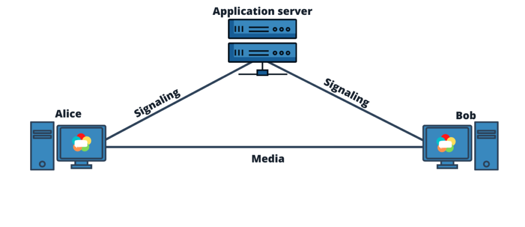
WebRTC was initially envisioned as a purely peer-to-peer technology. It was designed to send media directly between users via browsers. In the peer-to-peer connection, two users are connected by establishing a signaling connection to the application server, using a signaling server. Here, all data is exchanged between the peers without using any media server.
There is no fixed protocol or method specified within the WebRTC for the exchange of media, thus an existing method needs to be adopted. For instance, SIP, WebSockets, XMPP, Socket.IO, etc. These servers hold the business logic. They are intermediaries for the Session Description Protocol (SDP) exchange. Once the SDP exchange is complete, direct media communication between peers can start.
- Peer-to-peer
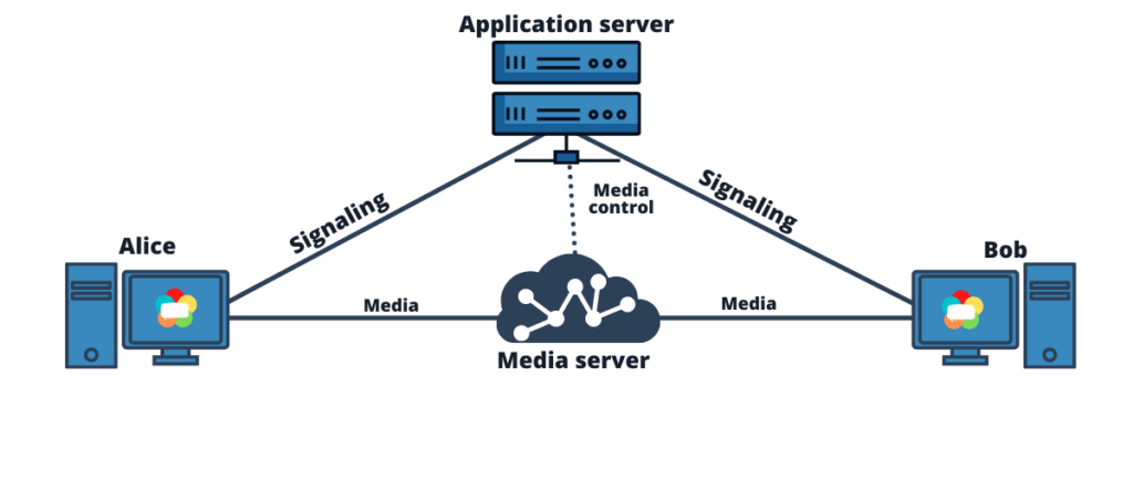
The idea behind WebRTC technology is to enable browser-to-browser communication. But, later on, there came a growing number of use cases where media is anchored in the network to act as a media peer. (Also known as Peer-to-Server).
Just like peer-to-peer, in the peer-to-server architecture also the users establish a signaling connection to the application server. Here, the application server keeps on managing the business logic but also utilizes a media control connection. This is for the SDP exchange between the client and the media server. As the exchange of SDP completes, media communication between servers begins.
- Peer-to-server
Simply put, to support group calls and other features like call recording and transcription, media servers are needed to handle the traffic. Now, this leads us to media servers. There are two types of media servers: SFUs and MCUs. Let’s discuss the two.
MCUs – Multipoint Control Units
The basic functionality of MCUs is shown in the below diagram.
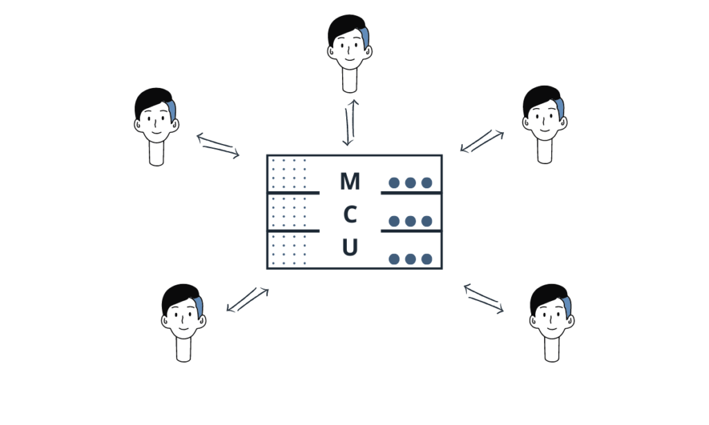
In MCU architecture, all users establish a connection with the MCU server to share the media (audio/video). The MCU then makes a composite media stream containing all of the video/audio from each user and sends that back to all members. Participant’s computers need not do much work as MCU contains most of the logic and very little intelligence is required at the device endpoint. So much so that MCU can generate output streams with different quality depending on the receiver’s down-link conditions. Regardless of the number of peers in the call, each participant gets a single set of media.
Choose an MCU when –
- You need very predictable bandwidth costs.
- You want to interface with a telephony system or other external systems.
- You want to give a composite stream to the devices having serious bandwidth constraints.
SFUs – Selective Forwarding Units
A group call on an SFU looks different, from MCU. Here is how it functions.
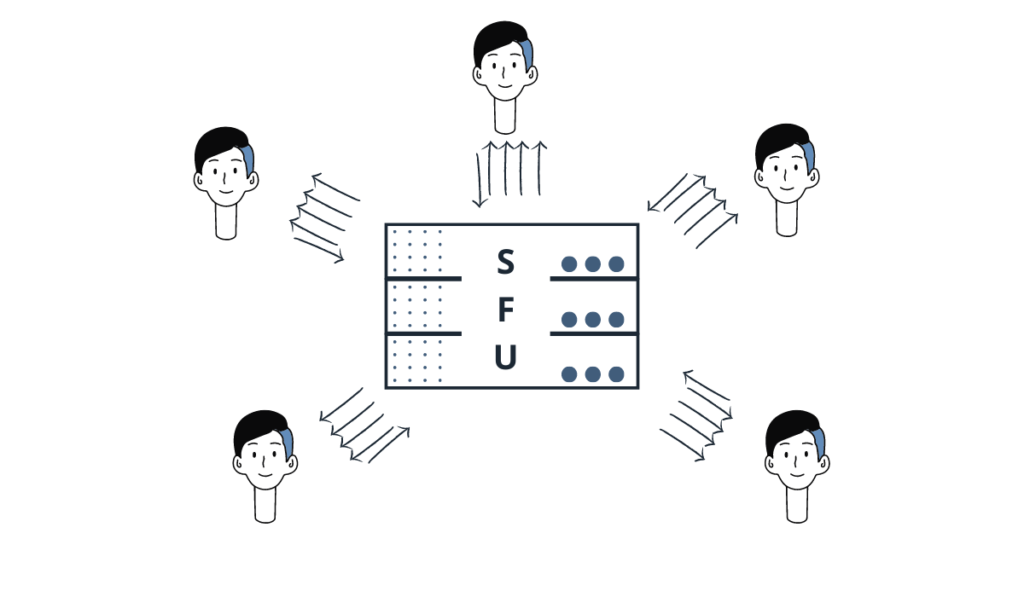
In SFU architecture, each participant still sends just one set of media, similar to MCU. But, the SFU does not make any composite streams. Instead, it sends a different stream to each user. See in the fissure. Since there are 5 people in the call, 4 streams are received by each participant.
There is less work on each participant as compared to the original peer-to-peer model. This is because each peer is only establishing only one connection (to the SFU) instead of connecting with each participant.
The best thing is SFU does not need to decode and re-code received streams. It acts as a forwarder of streams between the peers. This saves a lot of time. Besides, SFU offers an architecture that doesn’t break as easily as Mesh and with a lower cost than MCU.
Choose an SFU when –
- You want to work with asymmetric bandwidth or higher downlink bandwidth.
- You need scalability and want to add new streams.
There are scenarios where both media servers can be used, which we can describe to you over a call. The expert team of RTCweb.in has acquired years of experience in building live video applications. We can efficiently work with media servers and help you build a peer-to-server architecture. Contact us today to build yours!